
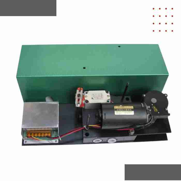
24EJF-P Electric Grease Directional Valve | 4/2 Way Valve for Dual-Line Centralized Lubrication Systems
$ 36.00
Product Overview The 24EJF-P Electric Grease Directional Valve is a precision-engineered, high-pressure directional control valve designed specifically for dual-line centralized lubrication systems. This electrically actuated two-position, four-way (4/2) valve provides reliable switching control of grease and heavy oils, ensuring optimal lubricant distribution to critical machinery components in demanding industrial environments. Built to withstand extreme operating conditions, the 24EJF-P combines robust construction with precise control, making it the ideal choice for steel mills, mining operations, cement plants, power generation facilities, and heavy manufacturing industries where equipment reliability is paramount. Core Applications: Dual-line automatic lubrication systems requiring high-pressure directional switching for grease NLGI 0-3# or heavy oils ISO VG 68 . Complete Technical Specifications Hydraulic Performance Parameters Parameter Specification Unit Valve Type 4/2 (Two-position, Four-way) – Alternative Configurations 3/2, 2/2 (via port blocking) – Maximum Operating Pressure 400 bar (40 MPa) Minimum Operating Pressure 10 bar (1 MPa) Rated Flow Capacity 8-12 L/min Pressure Drop @ Rated Flow ≤5 bar Switching Response Time 0.5-1.5 seconds Internal Leakage Rate ≤3 drops/min @ max pressure – Proof Pressure 600 bar (1.5× rated) Burst Pressure >800 bar Lubricant Compatibility Parameter Specification Grease NLGI Grade 0#, 1#, 2#, 3# Oil Viscosity Range ISO VG 68 – VG 460 Media Temperature Range -20°C to 80°C (-4°F to 176°F) Ambient Temperature Range -20°C to 80°C (-4°F to 176°F) Compatible Base Types Lithium, calcium, synthetic, mineral oil-based Electrical Specifications Parameter AC Model DC Model Voltage Options 110V / 220V / 380V AC 12V / 24V / 48V DC Frequency 50/60 Hz – Power Consumption 40-60 W 35-50 W Motor Type AC induction motor Permanent magnet DC motor Duty Cycle 100% (continuous operation) 100% (continuous operation) Insulation Class F (155°C) F (155°C) Protection Rating IP65 (standard), IP67 (optional) IP65 (standard), IP67 (optional) Electrical Connection Cable gland M20×1.5 Cable gland M20×1.5 Standard Cable Length 2 meters 2 meters Mechanical Construction Data Parameter Specification Unit Port Size Options G1/4″, G3/8″, G1/2″ – Port Connection Type BSPP, BSPT, NPT (optional) – Valve Body Material Carbon steel (std), SS316L (opt) – Spool Material Hardened alloy steel, ground finish – Seal Material Options NBR (std), FKM/Viton (high temp), HNBR – Mounting Configuration Flange mount, threaded mount – Net Weight 4.5 – 6.5 kg (configuration dependent) kg Overall Dimensions (L×W×H) 180 × 95 × 145 mm (nominal) mm Performance & Reliability Data Parameter Specification Switching Cycle Life ≥5,000,000 cycles @ rated pressure MTBF (Mean Time Between Failures) >50,000 operating hours Position Indication Visual indicator (std), proximity switch (opt) Manual Override Mechanical emergency operation available Vibration Resistance 5g @ 10-200 Hz (IEC 60068-2-6) Shock Resistance 50g, 11ms duration (IEC 60068-2-27) Port Configuration Standard 4/2 Flow Path Configuration: Port P: Pressure inlet (from lubrication pump) Port A: Outlet to distribution line A Port B: Outlet to distribution line B Port R: Return/vent port Operating Positions: Position 1: P→A, B→R (Line A pressurized) Position 2: P→B, A→R (Line B pressurized) How It Works: Operating Principle The 24EJF-P employs a precision spool valve mechanism to control lubricant flow direction in dual-line systems: Switching Cycle Position 1 – Line A Active (Energized): The electric motor drives the hardened steel spool to Position 1, connecting the pressure port (P) from the pump directly to outlet port A. Simultaneously, outlet port B connects to the return/vent port (R), allowing line B to depressurize. High-pressure grease flows through line A to all connected progressive distributors or injectors. Position 2 – Line B Active (De-energized/Alternate): When the control signal changes, the motor shifts the spool to Position 2. Now pressure port P connects to outlet port B, while outlet port A vents through return port R. Grease flow redirects to line B, serving the alternate set of lubrication points. Alternating Operation: The system controller alternates valve positions at programmed intervals (typically 5-30 minutes per cycle), ensuring complete and reliable lubricant distribution to all points. This alternating pressure principle enables a single pump to serve hundreds of lubrication points using only two main supply lines. Key Features & Engineering Advantages Design Excellence ✓ Hardened Steel Spool – Precision ground to ±5μm tolerance for minimal internal leakage and extended service life ✓ Multi-Lip Seal System – Redundant sealing technology prevents lubricant bypass under extreme pressure ✓ Positive Detent Positioning – Spring-loaded mechanism ensures stable, leak-free positioning between cycles ✓ Integrated Filtration – Built-in 100-mesh (149μm) screen protects internal components from contamination ✓ Thermal Compensation Design – Accommodates thermal expansion across full temperature range without performance loss ✓ Corrosion Protection – Zinc-nickel plating (10-15μm) provides superior resistance to harsh environments Performance Benefits 400 Bar Pressure Rating: Handles long-distance distribution and viscous lubricants without compromise Fast Switching Response: Sub-2-second actuation minimizes system cycle time and downtime Wide Viscosity Range: Reliably switches grease NLGI 0-3# and oils up to ISO VG 460 Low Pressure Drop: Optimized internal passages maintain system efficiency (≤5 bar @ rated flow) Proven Durability: 5 million cycle life in continuous industrial service Energy Efficient: 40-60W power consumption reduces operational costs Universal Compatibility: Integrates with all major centralized lubrication system brands Industrial Applications Steel & Metalworking Rolling mills (work rolls, backup rolls, pinch rolls) Continuous casting machines (segment bearings, guide rolls) Coiling/uncoiling equipment Shear and slitter lines Mining & Quarrying Primary crushers (jaw, gyratory, cone crushers) Secondary crushers and impact mills Grinding mills (SAG mills, ball mills) Conveyor systems (drive units, idlers) Mobile equipment (excavators, draglines) Cement Production Rotary kilns (pier bearings, thrust assemblies) Raw mills and cement mills Clinker coolers and preheaters Material handling systems Power Generation Coal handling equipment Ash handling systems Cooling tower gearboxes Auxiliary drive systems Heavy Industry Port equipment (ship loaders, gantry cranes) Paper mills (press sections, dryer cans) Automotive manufacturing lines Bulk material handling systems Installation Guidelines Mounting Requirements Preferred Orientation: Vertical mounting with motor on top allows optimal lubricant drainage and air venting. Horizontal mounting acceptable if return port faces downward. Support: Valve must be independently supported – do not allow pipe loads to stress valve body. Use dedicated mounting bracket or support frame. Clearance: Maintain minimum 150mm clearance around valve for maintenance access and heat dissipation. Port Size Selection Guide G1/4″ (DN8): Pump flow ≤6 L/min, distribution line length ≤50m G3/8″ (DN10): Pump flow 6-10 L/min, distribution line length 50-100m G1/2″ (DN15): Pump flow >10 L/min, distribution line length >100m Connection Best Practices Piping: Use seamless steel tubing (DIN 2391 or ASTM A519) with appropriate wall thickness per ISO 3305 Thread Sealing: Apply anaerobic thread sealant (e.g., Loctite 577) for metal-to-metal seals. Avoid PTFE tape on high-pressure connections. Pressure Monitoring: Install 0-600 bar glycerin-filled pressure gauges on both outlet lines (A & B) for system health monitoring. Electrical Connection Cable Requirements: AC models: H07RN-F flexible cable, minimum 1.5mm² conductor DC models: H07V-K cable, minimum 2.5mm² for voltage drop management Overcurrent Protection: AC 110/220V: 2-4A circuit breaker, C-curve AC 380V: 1-2A circuit breaker, C-curve DC 12/24V: 5-10A fuse/breaker DC 48V: 3-5A fuse/breaker Grounding: Connect valve body to protective earth using minimum 4mm² conductor. System Integration Compatible Control Systems The 24EJF-P integrates with PLCs (Siemens, Allen-Bradley, Schneider, Mitsubishi), dedicated lubrication controllers (Lincoln, SKF, Beka, Graco, Bijur Delimon), SCADA/HMI systems, and machine control panels. Control Signal Requirements Input Signal: AC models: 110/220/380V AC, minimum 100ms pulse width DC models: 12/24/48V DC, minimum 100ms pulse width Signal type: Simple relay contact or solid-state output Maximum switching frequency: 120 cycles/hour for continuous duty Optional Position Feedback Proximity Switch Package: Inductive sensor with PNP or NPN output provides valve position confirmation to PLC/controller for fault detection and alarm generation. M12 connector, 4-pin configuration. Quality Standards & Certifications Compliance Standard/Directive Compliance Status CE Marking EN 60204-1, EN 61000-6-2, EN 61000-6-4 RoHS Directive 2011/65/EU compliant REACH Regulation EC 1907/2006 compliant Quality Management ISO 9001:2015 certified manufacturing Pressure Equipment 2014/68/EU (Category SEP) ATEX (Optional) II 2G Ex d IIB T4 Gb (Zone 1/2) Factory Testing Each valve undergoes comprehensive testing including dimensional inspection, hydrostatic pressure test to 600 bar, zero-leakage verification, 1,000-cycle functional test, and electrical safety testing. Complete documentation with serial number traceability provided. Maintenance Requirements Service Schedule Monthly: Visual inspection for leaks, check electrical connections Quarterly: Inspect seals and verify pressure readings Semi-Annual: Internal inspection and seal condition assessment Annual: Complete seal replacement and full function test Recommended Spare Parts Complete seal kit (all O-rings and gaskets) Spool assembly (for major overhauls) Motor assembly (field replaceable) Stock Recommendation: Keep 1 complete seal kit per 5 installed valves. Available Configurations Model Options Body Materials: Carbon steel (standard) Stainless steel 316L (corrosive environments) Seal Materials: NBR (standard, -20°C to 80°C) FKM/Viton (high temperature, chemical resistance) HNBR (enhanced oil resistance) Protection Ratings: IP65 (standard industrial) IP67 (washdown/high moisture) Optional Features: Position sensing switches (PNP/NPN output) Manual override mechanism ATEX certification for hazardous locations Cold weather package (-40°C operation) Model Number Format 24EJF-P – [Port Size] – [Voltage] – [Options] Example: 24EJF-P-G3/8-AC220-IP67 (G3/8″ ports, 220V AC motor, IP67 protection) FAQ What is a 24EJF-P valve? A 24EJF-P valve is an electric directional valve used in grease and oil lubrication systems. It helps switch the flow direction in centralized lubrication setups and is commonly used in dual-line systems. What is the main function of a 24EJF-P valve? The main function of a 24EJF-P valve is to control and reverse lubricant flow between lines in a lubrication system. This allows lubricant to be distributed properly to different sections of the equipment. Where is a 24EJF-P valve used? It is used in centralized lubrication systems, dual-line lubrication systems, and industrial machinery that requires controlled flow direction. It is suitable for grease and oil applications under high-pressure conditions. What pressure can a 24EJF-P valve handle? According to the product information, the valve is designed for operating pressure up to 40 MPa. This makes it suitable for demanding industrial lubrication systems. How does a 24EJF-P valve work? The valve uses an electric motor to move the spool and switch the flow direction. When the system sends a signal, the motor rotates, the spool moves, and the valve changes the lubricant path automatically. Can a 24EJF-P valve be used with both grease and oil? Yes, the valve is suitable for both grease and oil lubrication systems. It is designed to work with lubricants used in centralized and dual-line applications. What are the benefits of using a 24EJF-P valve? The valve offers fast switching, reliable flow control, and strong performance in harsh working conditions. It also helps improve lubrication consistency and system efficiency. How should a 24EJF-P valve be installed? The valve should be installed on the main or branch pipe of the lubrication system in a location that is easy to inspect and maintain. It should also be placed where the movement mechanism is not obstructed. How should a 24EJF-P valve be maintained? Maintenance should include checking electrical connections, inspecting the spool movement, and making sure the valve body and lines are clean. Regular inspection helps prevent switching failures and downtime. What should I avoid when using a 24EJF-P valve? You should avoid installing the valve in a place with poor access, using it outside its pressure range, and ignoring electrical or mechanical wear. Proper installation and regular checks help extend service life. Technical Documentation Available for Download: Complete technical datasheet with performance curves Installation and commissioning manual 3D CAD models (STEP, IGES formats) 2D dimensional drawings (DXF, PDF) Electrical wiring diagrams Maintenance and troubleshooting guide For application assistance, custom configurations, or technical inquiries, please contact our technical sales team.