
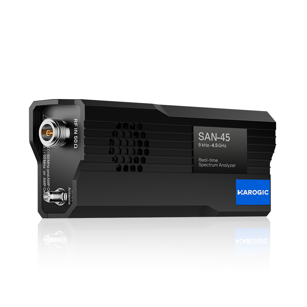
Spectrum Analyzer USB SAN-45 9kHz to 4.5GHz
$ 97.46
Spectrum Analyzer SAN Series KEY FACTS High-performance superheterodyne receiver Frequency range: 9 kHz to 4.5/6/9 GHz IF and image rejection: >95 dBc (typ.) 1 GHz DANL: -168 dBm/Hz (typ.) 1 GHz phase noise: <-110 dBc/Hz @ 10 kHz (typ.) 1 GHz phase noise measurement: <-125 dBc/Hz @ 10 kHz (typ.) Analysis bandwidth: 50 MHz / 100 MHz (opt. 50) (typ.) Whole unit weighs just 420 grams / 163 x 66 x 37 mm Benefits Highlight New HAROGIC SAN Series is a USB-based spectrum analyzer and receiver featuring a frequency range of 9 kHz up to 9 GHz. Designed to deliver high performance on a budget, the series includes essential measurement functions such as channel power, automatic harmonics, phase noise, and AM/FM analog demodulation. Furthermore, its highly compatible APIs facilitate seamless secondary development, offering customers exceptional versatility and value. 14-channel high-performance preselectionEffectively blocks false signals and interference Image rejection ≥95 dBc Intermediate frequency rejection ≥95 dBc Amplitude (dBm) Superior Performance-Everything You Need in One Place 1 GHz phase noise measurement -125 dBc/Hz @ 10 kHz Single-sideband phase measurement noise (dBc/Hz) Precision ClockBuilt-in GNSS positioning and timing Initial frequency accuracy ≤0.5 ppm Maximum GNSS correction accuracy ≤0.05 ppm Frequency calibration made easy No more worries about time base drift Comprehensive Measurement Modes to Meet Every Need Standard Spectrum Analysis mode IQ Streaming mode Power Detection Analysis mode Real-Time Spectrum Analysis mode Phase Noise Measurement Basic Vector Modulation Analysis mode (opt.71) Pulse Analysis (opt.72) Harmonic Analysis mode Mapping mode Main Functions Overview Channel Power OBW ACPR IM3 SEM AM/FM Demodulation Antenna Factor Amplitude Offset Signal Track Peak Table Data Record and Playback Multiple Unit Display Specifications* Frequency SAN-45 SAN-60 SAN-90 Frequency range 9 kHz to 4.5 GHz 9 kHz to 6 GHz 9 kHz to 9 GHz Reference clock Internal or external, manual correction or GNSS calibration is available Frequency accuracy TCXO (std.) <0.5 ppm, manual correction is available OCXO (opt.01) <0.2 ppm, manual correction is available Frequency correction via GNSS <0.05 ppm when GNSS is locked Aging and temperature stability TCXO (std.) <1 ppm/year, <1 ppm OCXO (opt.01) <1 ppm/year, <0.15 ppm Built-in GNSS 1PPS accuracy ± 100 ns Spectrum Purity SSB phase noise (dBc/Hz)Guaranteed/Typical Carrier frequency 1 GHz 4.5 GHz 6 GHz 9 GHz 100 Hz -85 / -88 -78 / -81 -75 / -78 -74 / -77 1 kHz -97 / -99 -90 / -93 -86 / -89 -88 / -91 10 kHz -110 / -112 -103 / -106 -100 / -103 -99 / -102 100 kHz -114 / -115 -104 / -107 -104 / -107 -99 / -102 1 MHz -131 / -132 -119 / -122 -118 / -121 -116 / -119 Residual response (dBm)RBW = 1 kHzGuaranteed/Typical Reference level (R.L.) 0 dBm -50 dBm 9 kHz to 100 MHz -90 / -94 -115 / -117 100 MHz to 4.5 GHz -90 / -95 -120 / -128 4.5 GHz to 6 GHz -90 / -96 -120 / -130 6 GHz to 9 GHz -90 / -98 -120 / -129 Image rejection >90 dBc, >95 dBc (Typical) IF rejection >90 dBc, >95dBc (Typical) Local oscillator related spurious <-65 dBc Center frequency ± (N/M) × 125 MHz, N, M = 1, 2, 3, 4, 5… IIP3/IIP2 (dBm)Typical Carrier frequency 1 GHz 4.5 GHz 6 GHz 9 GHz R.L. = 20 dBm 42/80 37/80 32/80 36/80 R.L. = 0 dBm 23/80 22/80 20/80 14/80 R.L. = -20 dBm 3/60 3/45 -1/45 -5/45 Amplitude Max. input power (CW) 23 dBm 50 MHz to maximum frequency and preamplifier is off 10 dBm 9 kHz to 50 MHz or preamplifier is on Max. DC voltage ±10 VDC Display range DANL to 30 dBm Level accuracy ± 1.0 dB from 20 oC to 30 oC typical conditions ± 1.5 dB over full temperature range all conditions IF in-band flatness < ±1.5 dB 50MHz analysis bandwidth < ±2.0 dB 100MHz analysis bandwidth Reference level -70 dBm to 23 dBm RF preamplifiers Auto or manual VSWR <2.0:1 Nominal, 90 MHz to Max. Frequency Display average noise level (DANL)dBm/Hz Guaranteed/TypicalRBW=1kHz SAN-45 SAN-60 SAN-90 Reference level -20 dBm -70 dBm -20 dBm -70 dBm -20 dBm -70 dBm 9 kHz to 1 MHz -131 / -134 -141 / -144 -131 / -134 -141 / -144 -131 / -134 -141 / -144 1 MHz to 100 MHz -151 / -154 -163 / -166 -151 / -154 -163 / -166 -151 / -154 -163 / -166 100 MHz to 3.0 GHz -141 / -144 -165 / -168 -141 / -144 -165 / -168 -141 / -144 -165 / -168 3.0 GHz to 4.5 GHz -142 / -145 -165 / -168 -142 / -145 -165 /-168 -142 / -145 -165 / -168 4.5 GHz to 6 GHz – – -143 / -146 -165 / -168 -143 / -146 -165 / -168 6 GHz to 9 GHz – – – – -144 / -147 -164 / -167 Standard Spectrum Analysis Detector PosPeak, NegPeak, Sample, Average, RMS, MaxPower RBW 0.1 Hz to 10 MHz VBW 0.1 Hz to 10 MHz Data chart SAStudio4 software provides spectrum, spectrogram, historical trace Measurements Channel power, OBW, X dB bandwidth, Adjacent channel power ratio, IM3 Sweep Speed RBW = 250 kHz FPGA processing > 1 THz/s RBW = 25 kHz FPGA processing > 300 GHz/s RBW = 1 kHz CPU processing > 4 GHz/s IQ Recording Continuous recording bandwidth Maximum: 50 MHz Burst recording bandwidth Maximum: 50 MHz / 100 MHz (opt.50)The built-in memory depth is 128 Mbytes IQ sample rate Maximum: 62.5 MSPS / 125 MSPS (opt.50)Decimate factor: 1, 2, 4, 8, 16, 32, 64, 128, 256, 512, 1024, 2048 External trigger response Maximum frequency response: 500 times/s Detection Analysis Min. time resolution 16 ns / 8 ns (opt.50) Max. analysis bandwidth 50 MHz / 100 MHz (opt.50) Detector PosPeak, NegPeak, Sample, Average, RMS, MaxPower Real Time Spectrum Analysis FFT analysis FFT engine is implemented in FPGA. Frame compression and trace detection are supported. No missing samples between FFT framesFFT frame update rate = 10 ^ 9 ns/(N × D × Minimum time resolution)POI = 2 × N × D × Minimum time resolutionN for FFT points (4096, 2048, 1024, 512, 256, 128, 64, 32)D for decimate factor (1, 2, 4, 8…) Typical settings FFT refresh rate (times/s) 100%POI (us) std. opt.50 std. opt.50 N = 4096, D = 1 15258 30517 131.072 65.536 N = 32, D = 1 1,953,125 3.906,250 1.024 0.512 Max. analysis bandwidth 50 MHz / 100 MHz (opt.50) Window function B-Nuttall, Flat-top, LowSideLobe, Kaiser RBW steps ≥12 grades Amplitude resolution 0.5 dB General Input and output RF input N(F), impedance 50 Ω Power Type-C, 5V 3A supply capacityvoltage range 4.75 to 5.25 V, ripple less than 200 mVp USB port Type-C, USB3.0 (USB2.0 bandwidth limited) Requires 5V 0.9A power supply External trigger input Integrated in AUXIO, 3.3V CMOS, high impedance Trigger output Integrated in AUXIO, 3.3V CMOS GNSS antenna input SMA (F) Analog IF output MMCX (F), maximum output power -25 dBmimpedance 50 Ω, 312.5 MHz ± 50 MHz External reference clock input MMCX(F), 10 MHz, Amplitude ≥ 1.5 Vpp, impedance 330 Ω Reference clock output MMCX(F), 100 MHz, Amplitude ≥ 0.3 Vpp, programmable on/off Overall / core weight ≤ 420 g / ≤ 195 g Overall / core dimensions (L × W × H) ≤ 163 x 66 x 37 mm / ≤ 109 x 50 x 16 mm Power consumption ≤ 20 W Packaging accessories Flash disk * 1, USB 3.0 data cable * 1, USB power cable * 1, Power adapter * 1 System requirements Windows 11/10/8/7(x86, x64), Debian 12/11/10(x64, AArch64)Ubuntu 24.04/22.04/20.04/18.04(x64, AArch64) Operating/Storage temperature (Ambient) T0 class (std.)T1 class (opt.40)T2 class (opt.41), only core 0 to 50 ℃ / -20 to 70 ℃-20 to 65 ℃ / -40 to 85 ℃-40 to 65 ℃ / -40 to 85 ℃ Operating relative humidity Ambient Temp.: 0 to 40 ℃Ambient Temp.: >40 ℃ 5 to 75%5 to 45% Phase Noise Measurement Min. frequency offset 1 Hz Max. measurement frequency offset 10 MHz Trace smooth Support SSB phase noise (dBc/Hz)Guaranteed/Typical Carrier frequency 1 GHz 4.5 GHz 6 GHz 9 GHz 100 Hz -90 / -94 -80 / -83 -80 / -83 -78 / -81 1 kHz -113 / -117 -102 / -105 -100 /-103 -95 / -98 10 kHz -120 / -125 -112 / -115 -109 / -112 -106 / -109 100 kHz -126 / -129 -114 / -117 -111 / -114 -108 / -111 1 MHz -136 / -139 -125 / -128 -123 / -126 -119 / -122 10 MHz -140 / -143 -137 / -140 -137 /-140 -136 / -139 Pulse Detection Min. pulse width 64 ns / 32 ns (opt.50) Measurement parameters Top Level, Base Level, Top/Base, Droop, OverShoot, Ripple, Rise Time, Rise Edge, Fall Time, Fall Edge, Width, PRI, Duty Cycle AM Demodulation Measurement parameters Modulation depth, carrier power, modulation rate, signal-to-noise ratio, RMS power, total harmonic distortion, etc. Modulation rate test range 20 Hz to 10 MHz Modulation rate test accuracy < 1 Hz when modulation rate < 1 kHz < 0.1% when modulation rate ≥ 1 kHz Modulation depth test range and accuracy 5% to 95%, ±5% (Nominal) FM Demodulation Measurement parameters Modulation frequency offset, carrier power, modulation rate, signal-to-noise ratio, RMS power, total harmonic distortion, etc. Modulation rate test range 20 Hz to 2 MHz Modulation rate test accuracy < 1 Hz when modulation rate < 1 kHz < 0.1% when modulation rate ≥ 1 kHz Frequency offset test range and accuracy 1 kHz to 10 MHz, ±6% (Nominal) Basic Vector Modulation Analysis Modulation type ASK: 2ASKFSK: 2FSK, 4FSKMSK: GMSKPSK: BPSK, QPSK, 8PSKQAM: 16QAM, 32QAM, 64QAM, 128QAM, 256QAM Symbol length 128 QAM and 256 QAM: 4000Others: 2000 Symbol rate (1/64 to 1/4) * sample rate, ≤ 32.5MSPS Filter Root raised cosine Filter roll-off factor 0.01 to 0.99 Display Spectrum, constellation, eye diagrams, measurement results Measurement EVM, amplitude error, phase error, frequency error, signal-to-noise ratio, part of the bitstream Downloads Product Manual PDF User Guide PDF Quick Start PDF Programming Guide PDF FAQ & Troubleshooting Guide PDF Driver